
We specialize in hard to find items

All Categories


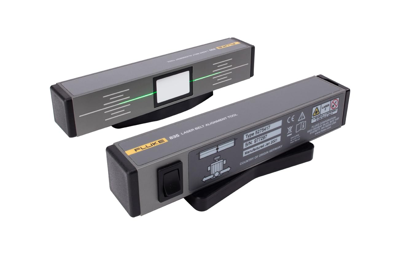
Fluke 835 - Laser Belt Alignment Tool
Share Tweet


Fluke 835 - Laser Belt Alignment Tool Features
-
835 Laser Belt Alignment Tool (with reflector)
-
Class II Laser, <1.0mW
-
Reflected laser technology doubles the distance, enhancing accuracy
-
Easy to use, one-person operation (tailor-made for pulley alignment jobs)
-
Leverages the proven OPTALIGN reflected beam principle for maximum angular resolution
About Fluke 835 - Laser Belt Alignment Tool
Fluke 835 - Laser Belt Alignment Tool Reflected laser technology doubles the distance, enhancing accuracy Easy to use, one-person operation (tailor-made for pulley alignment jobs) Strong magnets on the two units mount onto virtually any pulley face Leverages the proven OPTALIGN reflected beam principle for maximum angular resolution Time-saving method requires no cross-checking and shows offset, vertical, and horizontal angle simultaneouslyIt's a known factall rotating machinery are susceptible to misalignment. An aligned pulley system reduces belt wear, power losses, and vibration of machinery, leading to improved performance. Still using wires and straight edges to ensure your belt-drive machines are properly aligned? You could be losing thousands of dollars per year in replacement bearing and belt costs, hours of unnecessary repair time, and crippling unplanned downtime, not to mention taking years off your machine's useful life.Alignment of belt pulleys in four simple steps Initiate the Fluke 835 laser and mount the units on the faces to be aligned. The reflector should be mounted onto the machine to be moved (motor) while the laser transmitter is mounted on the stationary (driven) component. The position of the transmitted laser line on the reflector indicates vertical angularity and offset. Horizontal angularity is indicated by the position of the reflected laser line on the transmitter. Make adjustments while observing the laser lines on the reflector and the laser units: Correct vertical angularity by shimming moveable machine observing the correction on the reflector. Correct offset by shifting moveable machine axially observing the reflector unit. Correct horizontal angularity by shifting moveable machine horizontally observing correction on the laser unit. Genuine alignment is achieved when the transmitted laser line and the corresponding reflected laser line harmon